

How Do The Fringe Patterns Change With Different Slit Widths And Slit Separations?
Learning Objectives
By the stop of this section, you lot will be able to:
- Explicate the phenomena of interference.
- Ascertain constructive interference for a double slit and subversive interference for a double slit.
Although Christiaan Huygens idea that light was a moving ridge, Isaac Newton did not. Newton felt that there were other explanations for color, and for the interference and diffraction furnishings that were appreciable at the time. Owing to Newton's tremendous stature, his view generally prevailed. The fact that Huygens's principle worked was not considered evidence that was direct enough to prove that calorie-free is a moving ridge. The acceptance of the wave graphic symbol of lite came many years later when, in 1801, the English physicist and medico Thomas Immature (1773–1829) did his now-classic double slit experiment (meet Figure ane).
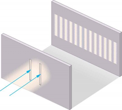
Figure 1. Young'south double slit experiment. Here pure-wavelength low-cal sent through a pair of vertical slits is diffracted into a pattern on the screen of numerous vertical lines spread out horizontally. Without diffraction and interference, the calorie-free would simply brand two lines on the screen.
Why do nosotros not commonly discover wave behavior for light, such as observed in Young'southward double slit experiment? Outset, light must interact with something pocket-sized, such equally the closely spaced slits used by Young, to prove pronounced wave effects. Furthermore, Immature first passed calorie-free from a single source (the Dominicus) through a unmarried slit to make the lite somewhat coherent. Past coherent, we mean waves are in phase or have a definite phase relationship. Incoherent means the waves accept random phase relationships. Why did Young and then pass the light through a double slit? The answer to this question is that 2 slits provide two coherent light sources that then interfere constructively or destructively. Immature used sunlight, where each wavelength forms its own pattern, making the effect more difficult to see. We illustrate the double slit experiment with monochromatic (single λ) light to clarify the effect. Figure two shows the pure constructive and destructive interference of 2 waves having the same wavelength and amplitude.
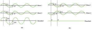
Figure 2. The amplitudes of waves add. (a) Pure constructive interference is obtained when identical waves are in phase. (b) Pure destructive interference occurs when identical waves are exactly out of phase, or shifted past one-half a wavelength.
When light passes through narrow slits, it is diffracted into semicircular waves, as shown in Figure 3a. Pure constructive interference occurs where the waves are crest to crest or trough to trough. Pure destructive interference occurs where they are crest to trough. The light must fall on a screen and exist scattered into our optics for us to run across the pattern. An analogous design for water waves is shown in Figure 3b. Note that regions of constructive and destructive interference move out from the slits at well-defined angles to the original axle. These angles depend on wavelength and the altitude between the slits, as we shall encounter beneath.
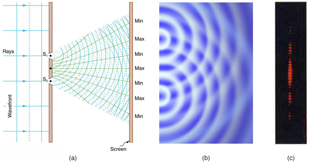
Effigy 3. Double slits produce ii coherent sources of waves that interfere. (a) Light spreads out (diffracts) from each slit, because the slits are narrow. These waves overlap and interfere constructively (bright lines) and destructively (nighttime regions). Nosotros can only see this if the calorie-free falls onto a screen and is scattered into our eyes. (b) Double slit interference pattern for water waves are nearly identical to that for light. Moving ridge action is greatest in regions of constructive interference and to the lowest degree in regions of destructive interference. (c) When light that has passed through double slits falls on a screen, we encounter a design such every bit this. (credit: PASCO)
To sympathise the double slit interference pattern, we consider how two waves travel from the slits to the screen, every bit illustrated in Figure four. Each slit is a different altitude from a given signal on the screen. Thus different numbers of wavelengths fit into each path. Waves starting time out from the slits in phase (crest to crest), but they may end up out of phase (crest to trough) at the screen if the paths differ in length past half a wavelength, interfering destructively as shown in Effigy 4a. If the paths differ by a whole wavelength, and then the waves make it in phase (crest to crest) at the screen, interfering constructively as shown in Figure 4b. More generally, if the paths taken by the ii waves differ past any half-integral number of wavelengths [(1/ii)λ, (3/ii)λ, (5/two)λ, etc.], then destructive interference occurs. Similarly, if the paths taken by the two waves differ by any integral number of wavelengths (λ, iiλ, iiiλ, etc.), and then constructive interference occurs.
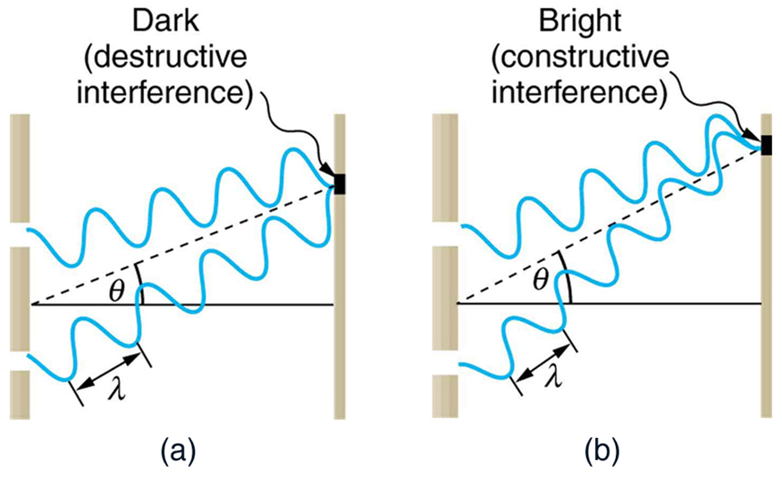
Effigy four. Waves follow different paths from the slits to a mutual point on a screen. (a) Destructive interference occurs here, because one path is a half wavelength longer than the other. The waves start in phase merely get in out of stage. (b) Constructive interference occurs here because 1 path is a whole wavelength longer than the other. The waves start out and make it in phase.
Have-Home Experiment: Using Fingers as Slits
Look at a light, such every bit a street lamp or incandescent bulb, through the narrow gap between two fingers held shut together. What blazon of blueprint do you see? How does it alter when y'all allow the fingers to move a little farther autonomously? Is it more than distinct for a monochromatic source, such every bit the xanthous calorie-free from a sodium vapor lamp, than for an incandescent bulb?
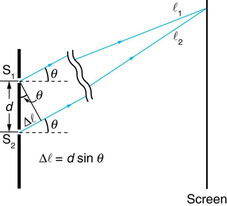
Figure five. The paths from each slit to a common betoken on the screen differ by an amount dsinθ, assuming the distance to the screen is much greater than the distance betwixt slits (not to scale here).
Effigy v shows how to make up one's mind the path length difference for waves traveling from ii slits to a common signal on a screen. If the screen is a large distance away compared with the distance between the slits, then the angle θ between the path and a line from the slits to the screen (see the figure) is nearly the same for each path. The difference betwixt the paths is shown in the figure; simple trigonometry shows it to be d sinθ, where d is the distance betwixt the slits. To obtain effective interference for a double slit, the path length difference must be an integral multiple of the wavelength, ord sinθ = mλ, for m = 0, 1, −i, 2, −2, . . . (constructive).
Similarly, to obtain destructive interference for a double slit, the path length difference must be a one-half-integral multiple of the wavelength, or
[latex]d\sin\theta=\left(m+\frac{1}{2}\right)\lambda\text{, for }m=0,ane,-1,ii,-2,\dots\text{ (destructive)}\\[/latex],
where λ is the wavelength of the light, d is the distance between slits, and θ is the angle from the original direction of the beam equally discussed higher up. We call k the order of the interference. For example, m= 4 is fourth-order interference.
The equations for double slit interference imply that a series of bright and dark lines are formed. For vertical slits, the low-cal spreads out horizontally on either side of the incident beam into a pattern called interference fringes, illustrated in Figure 6. The intensity of the bright fringes falls off on either side, existence brightest at the centre. The closer the slits are, the more is the spreading of the bright fringes. We can see this by examining the equationd sinθ = mλ, for m = 0, 1, −ane, 2, −two, . . . .
For stock-still λ and m, the smaller d is, the larger θ must be, since [latex]\sin\theta=\frac{1000\lambda}{d}\\[/latex]. This is consequent with our contention that wave effects are most noticeable when the object the moving ridge encounters (here, slits a distance d apart) is minor. Small d gives large θ, hence a large outcome.
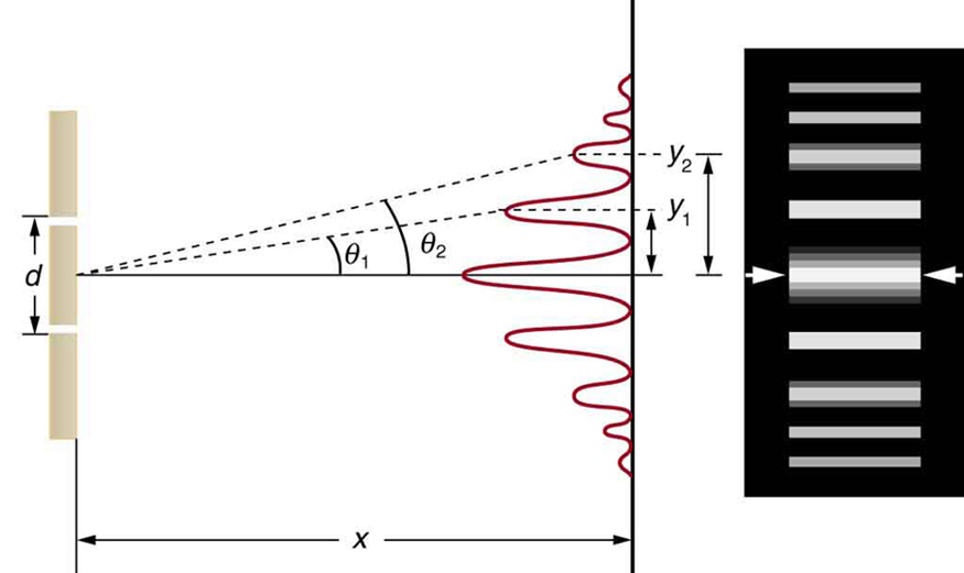
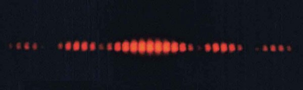
Figure 6. The interference design for a double slit has an intensity that falls off with angle. The photo shows multiple brilliant and dark lines, or fringes, formed by light passing through a double slit.
Case 1. Finding a Wavelength from an Interference Pattern
Suppose you pass light from a He-Ne laser through two slits separated by 0.0100 mm and find that the third bright line on a screen is formed at an angle of 10.95º relative to the incident beam. What is the wavelength of the lite?
Strategy
The third brilliant line is due to 3rd-order constructive interference, which means that k= 3. Nosotros are given d = 0.0100 mm and θ= 10.95º. The wavelength can thus be plant using the equationd sinθ = mλ for constructive interference.
Solution
The equation is d sinθ = mλ. Solving for the wavelength λ gives [latex]\lambda=\frac{d\sin\theta}{m}\\[/latex].
Substituting known values yields
[latex]\brainstorm{array}{lll}\lambda&=&\frac{\left(0.0100\text{ nm}\correct)\left(\sin10.95^{\circ}\right)}{3}\\\text{ }&=&6.33\times10^{-four}\text{ nm}=633\text{ nm}\end{assortment}\\[/latex]
Discussion
To three digits, this is the wavelength of lite emitted by the common He-Ne laser. Non past coincidence, this red color is similar to that emitted past neon lights. More important, nonetheless, is the fact that interference patterns tin can exist used to measure wavelength. Young did this for visible wavelengths. This analytical technique is still widely used to measure electromagnetic spectra. For a given order, the angle for constructive interference increases with λ, then that spectra (measurements of intensity versus wavelength) can exist obtained.
Instance ii. Calculating Highest Club Possible
Interference patterns exercise non have an space number of lines, since there is a limit to how large m can exist. What is the highest-order effective interference possible with the system described in the preceding example?
Strategy and Concept
The equationd sinθ = mλ (for one thousand = 0, 1, −1, 2, −two, . . . ) describes constructive interference. For fixed values of d and λ, the larger m is, the larger sinθ is. However, the maximum value that sinθ tin accept is 1, for an angle of 90º. (Larger angles imply that light goes backward and does not reach the screen at all.) Let us detect which grand corresponds to this maximum diffraction angle.
Solution
Solving the equationd sinθ = mλ for m gives [latex]\lambda=\frac{d\sin\theta}{thousand}\\[/latex].
Taking sinθ = 1 and substituting the values of d and λ from the preceding instance gives
[latex]\displaystyle{m}=\frac{\left(0.0100\text{ mm}\right)\left(1\right)}{633\text{ nm}}\approx15.8\\[/latex]
Therefore, the largest integer m can be is 15, orgrand= 15.
Give-and-take
The number of fringes depends on the wavelength and slit separation. The number of fringes will exist very large for big slit separations. However, if the slit separation becomes much greater than the wavelength, the intensity of the interference design changes so that the screen has ii bright lines cast by the slits, as expected when light behaves similar a ray. We likewise note that the fringes get fainter further away from the center. Consequently, not all 15 fringes may be appreciable.
Section Summary
- Young'south double slit experiment gave definitive proof of the wave graphic symbol of light.
- An interference pattern is obtained past the superposition of light from two slits.
- There is constructive interference whend sinθ = mλ (for thou = 0, 1, −i, ii, −2, . . . ), where d is the altitude betwixt the slits, θ is the angle relative to the incident direction, and m is the social club of the interference.
- At that place is subversive interference whend sinθ = mλ (for g = 0, 1, −1, 2, −2, . . . ).
Conceptual Questions
- Young'due south double slit experiment breaks a single light beam into two sources. Would the same pattern be obtained for 2 independent sources of light, such equally the headlights of a afar motorcar? Explain.
- Suppose you use the same double slit to perform Immature's double slit experiment in air and and then repeat the experiment in water. Do the angles to the same parts of the interference design get larger or smaller? Does the color of the light alter? Explicate.
- Is it possible to create a situation in which there is but destructive interference? Explicate.
- Figure 7 shows the central part of the interference pattern for a pure wavelength of reddish light projected onto a double slit. The design is actually a combination of unmarried slit and double slit interference. Note that the bright spots are evenly spaced. Is this a double slit or single slit characteristic? Notation that some of the vivid spots are dim on either side of the middle. Is this a single slit or double slit feature? Which is smaller, the slit width or the separation betwixt slits? Explain your responses.
Effigy seven. This double slit interference pattern also shows signs of unmarried slit interference. (credit: PASCO)
Issues & Exercises
- At what angle is the kickoff-order maximum for 450-nm wavelength bluish light falling on double slits separated by 0.0500 mm?
- Calculate the angle for the 3rd-order maximum of 580-nm wavelength yellow calorie-free falling on double slits separated past 0.100 mm.
- What is the separation between two slits for which 610-nm orangish light has its first maximum at an angle of 30.0º?
- Find the distance between two slits that produces the first minimum for 410-nm violet light at an angle of 45.0º.
- Summate the wavelength of light that has its 3rd minimum at an bending of 30.0º when falling on double slits separated by three.00 μm.
- What is the wavelength of light falling on double slits separated by 2.00 μm if the third-order maximum is at an angle of 60.0º?
- At what angle is the 4th-guild maximum for the situation in Question one?
- What is the highest-order maximum for 400-nm light falling on double slits separated by 25.0 μm?
- Find the largest wavelength of light falling on double slits separated by 1.20 μm for which in that location is a first-order maximum. Is this in the visible part of the spectrum?
- What is the smallest separation between ii slits that will produce a second-order maximum for 720-nm red light?
- (a) What is the smallest separation betwixt two slits that will produce a second-social club maximum for any visible calorie-free? (b) For all visible low-cal?
- (a) If the first-order maximum for pure-wavelength light falling on a double slit is at an angle of 10.0º, at what angle is the second-order maximum? (b) What is the bending of the first minimum? (c) What is the highest-society maximum possible hither?
- Figure 8 shows a double slit located a distance ten from a screen, with the distance from the center of the screen given by y. When the distance d between the slits is relatively large, in that location will exist numerous bright spots, chosen fringes. Prove that, for small angles (where [latex]\text{sin}\theta\approx\theta\\[/latex], with θ in radians), the altitude between fringes is given by [latex]\Delta{y}=\frac{10\lambda}{d}\\[/latex].
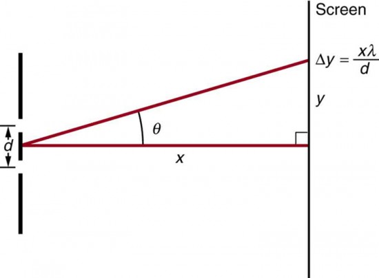
Figure viii. The distance betwixt next fringes is [latex]\Delta{y}=\frac{x\lambda}{d}\\[/latex], bold the slit separation d is large compared with λ.
- Using the result of the problem in a higher place, calculate the distance between fringes for 633-nm lite falling on double slits separated by 0.0800 mm, located 3.00 m from a screen equally in Figure 8.
- Using the upshot of the problem two bug prior, find the wavelength of lite that produces fringes seven.fifty mm apart on a screen 2.00 m from double slits separated by 0.120 mm (see Figure 8).
Glossary
coherent: waves are in phase or take a definite phase relationship
constructive interference for a double slit: the path length departure must be an integral multiple of the wavelength
destructive interference for a double slit: the path length difference must exist a half-integral multiple of the wavelength
breathless: waves accept random phase relationships
guild: the integer yard used in the equations for constructive and destructive interference for a double slit
Selected Solutions to Problems & Exercises
i. 0.516º
3. one.22 × ten−half dozen chiliad
5. 600 nm
7. 2.06º
9. 1200 nm (not visible)
eleven. (a) 760 nm; (b) 1520 nm
13. For small angles sin θ − tan θ≈ θ(in radians).
For two next fringes nosotros have,dsin θ m = mλ andd sin θ one thousand + 1 = (yard+ ane)λ
Subtracting these equations gives
[latex]\begin{array}{}d\left(\sin{\theta }_{\text{m}+1}-\sin{\theta }_{\text{1000}}\correct)=\left[\left(yard+1\right)-one thousand\right]\lambda \\ d\left({\theta }_{\text{m}+1}-{\theta }_{\text{m}}\right)=\lambda \\ \text{tan}{\theta }_{\text{thou}}=\frac{{y}_{\text{g}}}{x}\approx {\theta }_{\text{m}}\Rightarrow d\left(\frac{{y}_{\text{m}+1}}{x}-\frac{{y}_{\text{1000}}}{x}\right)=\lambda \\ d\frac{\Delta y}{x}=\lambda \Rightarrow \Delta y=\frac{\mathrm{10\lambda }}{d}\finish{array}\\[/latex]
15. 450 nm

Source: https://courses.lumenlearning.com/physics/chapter/27-3-youngs-double-slit-experiment/
Posted by: kintzelsishomistend.blogspot.com
0 Response to "How Do The Fringe Patterns Change With Different Slit Widths And Slit Separations?"
Post a Comment